Carburization inspection robots for radiant tubes inside ethylene cracking furnaces
Date : 01 Aug 2017
BOOK : HP-Hydrocarbonprocessing
ABSTRACT
In an olefins plant, the reliability of ethylene cracking furnaces is one of the deciding factors used to indicate whether or not the plant can be operated at its design productivity. If a furnace shutdown occurs due to a reliability-related issue, then ethylene productivity will drop and lead to opportunity loss, material and scaffolding costs, etc. For example, the cost of shutting down a furnace with an ethylene productivity of 4.5 tph (tons per hour) to replace one damaged radiant tube can exceed $300,000. These costs can skyrocket in the event of a fire. Thus, maintaining or enhancing the reliability of furnaces becomes one of the crucial tasks to enable a plant to achieve its productivity target.
In accordance with a reliability centered maintenance (RCM) program, the radiant tube- where feedstock such as naphth, liquefied petroleum gas (LPG), etc., is cracked-is considered one of the major components of a furnace due to its impact and the significant consequences when it fails to function.
1.Carburization
While numerous damage mechanisms can shorten the lifetime of the radiant tube,1 carburization is widely known as the major damage mechanism [2][3][4]. However, performing carburization inspection by using NACE TM0498-2006 may have some limitations, as this destructive test method is suitable when deep investigation of tube failure is required [6]. Tools and sensors for onsite carburization inspection have been developed to detect carburization without cutting the radiant tube [6][7]. This non-destructive test (NDT) method not only reduces time and resources for carburization inspection, but also significantly reduces the risk of radiant tube failure due to carburization, allowing users to identify and replace radiant tubes that are prone to failure. As a result, carburization inspection using an NDT method becomes a crucial task that should be periodically performed to assess the remaining life of radiant tubes.
2.Carburization inspection robot
A carburization inspection robot, shown in FIG. 1, has been developed to measure and collect carburization data from the radiant tube while the furnace is shut down. The robot is intentionally designed to not only replace the use of handheld carburization detectors to decrease labor hours used inside the confined working space for scaffolding work and carburization inspection, but also to reduce the health hazard of working high off the ground on scaffolds.
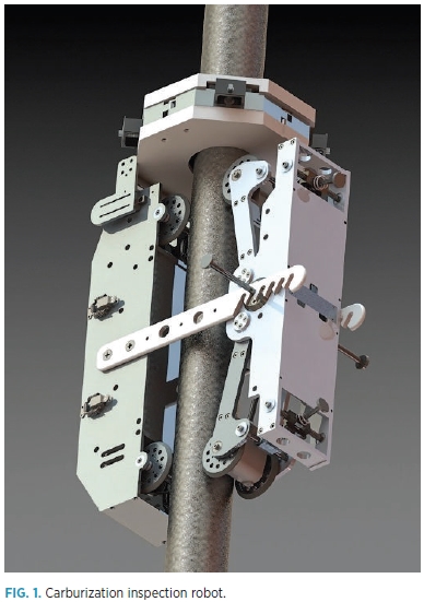
The carburization inspection robot is capable of climbing radiant tubes with outside diameters of 60 mm–160 mm at a speed of 3.5 m/min. The robot can be equipped with two or four sensors, depending on tube spacing. The minimum accessible tube spaces are 17 mm and 40 mm for two and four sensors, respectively. While the robot is moving along the external surface of the radiant tube, it simultaneously measures and collects a set of carburization data with a resolution of up to 1 cm, or up to 1,400 points/min, compared to a handheld carburization detector, which can measure and collect data at about 10 points/min. This means that the carburization inspection robot can increase detectability by approximately 140 times over the handheld detector, resulting in a substantial increase of detectability and a significantly reduced risk of tube failure due to carburization. A brief summary of the robot’s specifications is provided in TABLE 1.
TABLE1. Brief summary of robot specifications
|
Outside diameter |
60 mm - 160 mm |
|
Maximum number of carburization sensors |
4 |
|
Minimum accessible tube space
|
|
|
Average climbing speed |
3.5 m/min |
|
Resolution
|
|
3.Sensors and equations
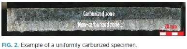
Each sensor attached to the robot is a Hall-effect sensor that responds to the magnetic field generated by phase change due to carburization. The higher the Cr depletion due to carburization, the higher the magnetic field generated. Applying this principle, the raw data measured by the Hall-effect sensors can be converted into the carburization depths. The process of determining an equation for converting the raw data into the carburization depths began with collecting the uniformly carburized specimens with various carburization depths from the furnaces. Then, macrostructural analysis was conducted to distinguish the carburized zone from the non-carburized zone, as shown in FIG. 2. The actual carburization depths were also measured at this step, and the sensors were used to measure the strength of the magnetic field of each specimen. Finally, the equation for converting the raw data from the sensors into the carburization depths was generated by fitting the curve to a series of raw data.
4.Validation
The most important process for utilizing sensors and creating equations is validation. Performing validations will test whether the sensors and the equations are able to detect carburization and are correctly and accurately measuring the carburization depth at each location. Three pieces of 45Ni - 35Cr specimens with a thickness of 6.4 mm and non-uniform carburization profiles (similar to the one shown in FIG. 3) were used during the validation process, which was performed by comparing the carburization profiles plotted by using the converted carburization depths (blue solid line in FIG. 3) with the carburization profiles plotted by using the actual carburization depths (red dotted line in FIG. 3).
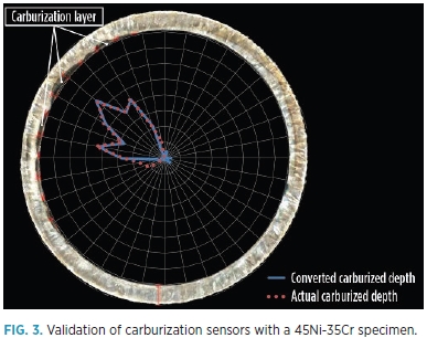
The results showed that the sensors were able to detect localized carburization. Moreover, at high degrees of carburization (the actual carburization depths of ≥ 0.5 mm, or 8% of the tube thickness), the converted carburization depths deviated approximately 10% from the actual carburization depths. At low degrees of carburization (the actual carburization depths of less than 0.5 mm), the 45Ni-35Cr specimens seemed to still be in non-ferromagnetic regime. Carburization is difficult to detect, and the accuracy of the converted depths seemed to decrease using the equation mentioned earlier. Regular service may be carried out on the radiant tubes when the carburization depth does not exceed 50% of the tube thickness, in accordance with API 573.8 Therefore, the carburization sensors are able to detect the locations of carburization and indicate the prone-to-failure areas due to carburization on the tubes.
5.Onsite inspection
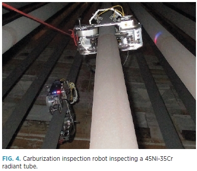
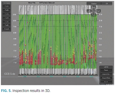
Normally, for a furnace with 4.5 tph of ethylene productivity, using the handheld carburization detector in carburization inspection requires two days for scaffolding erection and removal, and two additional days for the manual carburization inspection. Using the carburization inspection robot can save furnace downtime by eliminating scaffolding erection and removal. Furthermore, it takes only 1 d to complete the carburization inspection. The carburization inspection robot is attached to a radiant tube by coupling the driving side with the sensor side (FIG. 4) on the reference level to ensure that each measurement begins from the same level. The robot is controlled by an operator via a program in a laptop computer. It takes approximately 10 min. to inspect one pass of a radiant tube, including attaching and detaching the robot. Inspectors can monitor the carburization depths on the laptop computer to check whether any abnormalities in the measurements exist. The online monitoring allows the inspection team to solve any problems immediately. In FIG. 5, the results are shown in the 3D model, with a resolution
of 10 cm and a color scale (green = low degree of carburization; yellow = medium degree of carburization; and red = high degree of carburization). The 3D results and the color scale help users to easily and swiftly locate what needs to be replaced. This also allows users to not only know the present carburization profile of each pass, but also enables them to predict the carburization rate if the inspection is conducted regularly.
6.Benefits
Benefits of using the carburization inspection robots during the furnace shutdown fall into three major aspects: operation and maintenance, reliability and safety. The carburization
inspection robot can substantially reduce a carburization inspection by approximately 68 hr for a furnace with an ethylene production of 4.5 tph. This reduction is equivalent to more than 300 t of ethylene production, aside from the cost of radiant tube replacement. The cost of maintenance and scaffolding are also dramatically reduced. The detectability of the carburization inspection robot is
much better than the handheld carburization detector within the same timeframe, so users can gain more insights of the radiant tube’s condition, decide what countermeasures to use, and more accurately estimate the remaining life of the radiant tube. Finally, the carburization inspection robot can help olefins plants enhance human safety by decreasing time used in the confined space and reducing work at high elevation on the scaffold.
LITERATURE CITED
[1] “API RP 571: Damage mechanisms affecting fixed equipment in the refining industry,” American Petroleum Institute (API), 2nd Ed., API, 2011.
[2] Ul-Hamid, A., H. M. Tawancy, A.-R. I. Mohammed and N. M. Abbas, “Failure analysis of furnace radiant tubes exposed to excessive temperature,” Engineering Failure Analysis, Vol. 13, 2006.
[3] Shen, L., J. Gong, Y. Jiang and L. Geng, “Damage prediction of HP40Nb steel with coupled creep and carburization based on the continuum,” Acta Metallurgica Sinica (English Letters), Vol. 25, No. 4, August 2012.
[4] Wang, W., K. Liang, C. Wang and Q. Wang, “Comparative analysis of failure probability for ethylene cracking furnace tube using Monte Carlo and API RBI technology,” Engineering Failure Analysis, Vol. 45, 2014.
[5] “NACE TM0498-2014: Evaluation of the carburization of alloy tubes used for ethylene manufacture,” National Association of Chemical Engineers (NACE) Intl., 2006.
[6] Shinohara, T., I. Kohchi, K. Shibata, J. Sugitani and K. Tsuchida, “Development of nondestructive technique for measuring carburization thickness and of a new carburization-resistant alloy,” Materials and Corrosion, Vol. 37, No. 7, July 1986.
[7] Kasai, N., S. Ogawa, T. Oikawa, K. Sekine and K. Hasegawa, “Detection of carburization in ethylene pyrolysis furnace tubes by a C-core probe with magnetization,” Journal of Nondestructive Evaluation, Vol. 29, 2010.
[8] “API RP 573: Inspection of fired boilers and heaters,” American Petroleum Institute (API), 3rd Ed., API, 2013.